|
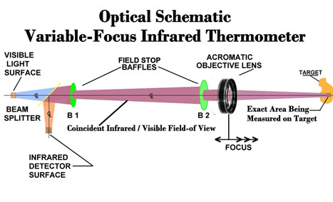
Figure 1 is the optical schematic of the Vario-Zooom variable-focus infrared
thermometer (US Patent No. 7,355,178).
|
|
 |
|
Figure 1
Optical Schematic of Variable Focus Infrared
Thermometer
|
| |
|
Visible Light Surface (VLS) |
The VLS is a Lambertian surface that is exactly
the same size, shape and texture as the Lambertian Infrared Detector Surface
(IDS). Visible wavelength “light” emanates from the VLS, either from direct
quantum radiation (e.g., LED) or from re-radiation from a backlit diffuser.
|
|
Infrared Detector Surface (IDS) |
The IDS is a planer array of thermocouples
connected with a square electrode pattern. The light emitting/collection area
of the IDS is the same size and shape as the VLS.
|
| Beam
Splitter |
The beam splitter is a bi-chromic “hot
mirror.” It transmits visible wavelengths of light with little attenuation
(≈10%). However, for incident infrared light wavelengths of greater than 2
micrometers, it is highly reflective (R ≥80%). Hence, the beam splitter passes
the visible light from the VLS and reflects the incident infrared light from the
optical system at an angle equal to its incident angle.
|
|
Positioning |
|
The normal centerline axis of the VLS must
coincide with the system’s centerline axis, and the VLS is located at the
system’s rear focus.
The beam splitter is normally located at a
convenient place along the optical axis and inclined at 45° to the axis.
The IDS is located to the side of the optical
axis in such a manner that its vertical centerline axis is positioned normal to
the optical system centerline axis and intersects it at the Cardinal point where
the beam splitter surface also intersects the system centerline axis.
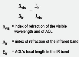
If the achromatic objective lens (AO) has the
same focal distance in the infrared wavelength band as in the visible band, then
the distances of the IDS and the VLS from the cardinal point are equal. If the
focal distances are different, then the distances are proportional to the
respective indices of refraction according to the formula:
|
|
|
|
Therefore, the differences in distance from IDS
to the beam splitter and VLS to the beam splitter is fir -
nvis. The longer distance will correspond to the smaller “n.” A
final positioning requirement of the integrating optics is that the orthogonal
axis of the beam splitter (the surface axis perpendicular to the page) must also
go through the cardinal point where the axes intercept.
As the VLS and the IDS beams leave the beam
splitter surface, their centerline axes are coincident in all respects and can
be considered geometrically as a single beam.
The single beam is shaped by baffle B1 and
directed to baffle B2, which is located very close to the objective lens when it
is positioned in the infinity focus position. The beam diameter is shaped by B2
to approximately 50% of the lens’ clear aperture.
|
| |
|
Variable Focus |
|
A primary requirement for a variable-focus
infrared thermometer is that the calibration factor, or temperature reading,
does not vary as the objective focal distance changes through its design range,
for targets of constant temperature.
This is assured by the fact that the beam from
B2, defined by B2, passes through the achromatic objective lens (AOL)
unobstructed for a wide range of final foci as determined by the axial position
of the AOL.
The beam from B2 continues to expand at the
same solid angle as it had when leaving B2 until it passes through AOL, which
focuses it onto the target spot.
Since AOL does not constrict the beam, it
carries the same optical power through B2 and on to the infrared detector for
any focus, as long as the beam diameter does not exceed the clear aperture (CA)
of AOL. This provides variable focal distances for the infrared thermometer
from infinity where the beam diameter is defined by B2, to twice the simple
focal length of AOL, defined by the CA of AOL.
|